Table of Contents
Introduction
If you have ever had a professional wireless network designed or installed — or read any detailed guide about enterprise Wi-Fi — you have encountered the phrase “PoE switch.” It appears in every access point specification sheet, every managed wireless deployment guide, and every professional network design document.
And yet it is one of the least explained components in the entire networking stack.
Most people understand what a router does. Most people understand what a Wi-Fi access point does. But a PoE switch — the device that sits between them, powering and connecting every access point in a professional network — is almost never explained in plain language for the people who are actually making purchasing and deployment decisions.
This article fixes that.
By the end, you will understand exactly what a PoE switch is, how it works, why it is essential to every professional wireless deployment, what the different standards mean, how to choose the right one for your specific environment, and what happens when you try to build a professional wireless network without one.
What Is a Switch? (A Quick Foundation)
Before we get to PoE specifically, it helps to understand what a network switch does in the first place — because this is where most explanations lose people.
A network switch is the device that connects multiple wired devices on a local network and manages the flow of data between them. Think of it as a traffic controller for your internal network. Your internet router connects your network to the outside world. Your switch connects all the devices within your network to each other — and to the router.
In a professional wireless network, the switch is the wired backbone. Every access point connects to the switch via an Ethernet cable. The switch connects to the router, which connects to your internet connection. Data flows from the internet → router → switch → access point → wireless device. And back.
In a small home setup, you might not have a dedicated switch — the router handles everything. But in any professional deployment with multiple access points, a dedicated switch is essential. It is the hub around which the entire wired infrastructure is organised.
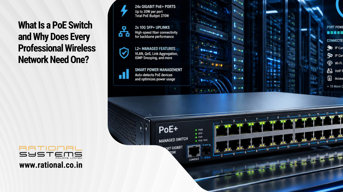
A PoE switch is simply a switch that can also deliver electrical power through those same Ethernet cables — eliminating the need for a separate power outlet at every access point location.
What Is PoE? Power Over Ethernet Explained
PoE stands for Power over Ethernet. It is exactly what it sounds like: the ability to deliver electrical power through an Ethernet cable at the same time as data.
A standard Ethernet cable — CAT5e, CAT6, or CAT6A — contains four pairs of twisted copper wires, for a total of eight conductors. In normal data transmission, two pairs are used for sending data and two for receiving it. PoE uses the electrical characteristics of those same pairs to carry DC power alongside the data signal, without interfering with the data transmission.
The practical result is that a single CAT6 cable running from a PoE switch to a Wi-Fi access point delivers both the network connection and the electricity the access point needs to operate. No separate power cable. No separate power adaptor. No power outlet required at the access point location.
This is not a minor convenience. It is an architectural capability that fundamentally changes how wireless networks can be designed and deployed.
Why PoE Matters for Wireless Network Deployment
To understand why PoE is so important, consider what deploying a professional wireless network without it actually looks like.
A large office building needs 12 access points, one per area across three floors. Without PoE, each access point needs:
- A CAT6 data cable running from the switch to the access point location
- A separate power cable running from a nearby electrical outlet to the access point
- An electrical outlet at or near each access point mounting location
- A power adaptor for each access point
In practice, this means an electrician must install electrical outlets at or near the ceiling at each of the 12 access point locations — locations that are typically chosen for optimal wireless coverage, not for proximity to existing power points. This adds significant cost, significant construction disruption, and significant time to every deployment.
With PoE, each access point needs exactly one thing: a single CAT6 cable running from the PoE switch to the access point location. That cable delivers both data and power. No electrician. No power outlets. No adaptor bricks dangling from ceiling tiles. No extension cords. Just one clean cable doing two jobs.
Power over Ethernet allows a single cable to provide both a data connection and enough electricity to power networked devices such as wireless access points, IP cameras, and VoIP phones.
For a 12 access point deployment, this translates to 12 fewer electrical outlet installations, 12 fewer power adaptors to purchase and manage, dramatically simpler cable management, significantly lower installation cost, and a cleaner, more professional finished installation.
For a school campus with 40 access points, or a hotel with 90 room-mounted access points, the difference is not just convenient — it is the factor that makes the deployment economically and practically viable.
The PoE Standards: What 802.3af, 802.3at, and 802.3bt Actually Mean
PoE is not a single technology. It is a family of IEEE standards that have evolved over two decades, each delivering more power than the last. Understanding these standards is essential for choosing the right switch for your specific access points and devices.
Power over Ethernet has revolutionized how modern networks deliver both data and electrical power over a single cable. PoE standards — IEEE 802.3af, 802.3at, and 802.3bt — define how much power can safely and efficiently travel through Ethernet cables. As connected devices demand higher wattage, PoE technology has evolved to keep pace — moving from PoE at 15.4W to PoE+ at 30W and finally PoE++ at up to 100W.
IEEE 802.3af — PoE (Original Standard, 2003)
Introduced in 2003, the first official Power over Ethernet standard delivers up to 15.4W from the Power Sourcing Equipment, with 12.95W available at the powered device after cable losses. It uses two pairs of Ethernet wires for power and data and is ideal for low-power devices like IP phones and basic cameras.
In 2026, 802.3af is the minimum baseline — relevant for legacy devices and simple IP phones but insufficient for modern Wi-Fi access points.
IEEE 802.3at — PoE+ (2009)
PoE+ (802.3at) provides up to 30 watts of power per port, with 25.5W available at the powered device after cable losses. It is suitable for wireless access points, advanced IP cameras, and some VoIP phones.
PoE+ is the standard that made professional wireless deployment genuinely practical. Most enterprise-grade access points from Ubiquiti UniFi, Aruba Instant On, and Cisco Meraki are designed to operate on PoE+ power budgets, making 802.3at switches the baseline for professional wireless deployments.
IEEE 802.3bt — PoE++ (2018)
The IEEE 802.3bt PoE standard was published to enable Ethernet cabling to deliver more power. The new standard increases the power transmitted through a single twisted pair cable from 25 watts in 802.3at to 90 watts in 802.3bt PoE.
802.3bt PoE++ has two types: Type 3 up to 60W and Type 4 up to 90–100W, suitable for high-power devices.
PoE++ is relevant for next-generation Wi-Fi 6E and Wi-Fi 7 access points with higher power requirements, outdoor access points with integrated heaters, high-resolution PTZ security cameras, and any device that draws more than 30W.
Here is the complete standards comparison in a single table:
| Standard | Name | Year | Power at Switch | Power at Device | Typical Use |
|---|---|---|---|---|---|
| 802.3af | PoE | 2003 | 15.4W | 12.95W | IP phones, basic cameras |
| 802.3at | PoE+ | 2009 | 30W | 25.5W | Wi-Fi APs, advanced cameras |
| 802.3bt Type 3 | PoE++ | 2018 | 60W | 51W | High-power APs, PTZ cameras |
| 802.3bt Type 4 | PoE++ | 2018 | 90–100W | 71.3W | Displays, industrial devices |
Backward compatibility: A PoE++ (802.3bt) switch can safely power PoE+ or PoE devices, automatically adjusting voltage and current. However, older PoE or PoE+ switches cannot power newer PoE++ devices requiring more than 30W. This flexibility makes network upgrades seamless — existing infrastructure can evolve gradually.
How a PoE Switch Actually Works
Understanding the mechanism behind PoE removes any concern about whether it is safe for devices that are not PoE-compatible.
Standards-based Power over Ethernet is implemented following IEEE specifications. The standards require Category 5 cable or better for high power levels. PoE supplies power as a common-mode signal over two or more of the differential pairs in Ethernet cables. This power comes from a PoE-providing device like an Ethernet switch or a PoE injector. This phantom power technique works with 10BASE-T, 100BASE-TX, 1000BASE-T, 2.5GBASE-T, 5GBASE-T, and 10GBASE-T.
The critical safety mechanism is the detection and classification process. Before a PoE switch applies any power to a port, it goes through a negotiation sequence with the connected device:
Detection: The switch sends a small test signal to the connected port. If the device responds with the correct resistance signature defined by the IEEE standard, the switch identifies it as a PoE-capable device. If there is no response — if a laptop, printer, or any non-PoE device is connected — the switch does not apply power. IEEE-compliant power sourcing equipment performs detection before applying voltage, ensuring non-PoE devices are not powered accidentally.
Classification: Once a PoE device is detected, the switch negotiates the power class — how much power the device needs. The device identifies itself as Class 0 through Class 8, each corresponding to a power range. The switch allocates the appropriate power budget for that port.
Power delivery: Only after successful detection and classification does the switch apply full operating voltage to the port. The data connection and power delivery then operate simultaneously through the same cable.
This is why you can safely connect a non-PoE device — a laptop, a printer, a desktop computer — to any port on a PoE switch without any risk. The switch will detect the absence of a PoE signature and operate that port as a standard data-only port.
Managed vs Unmanaged PoE Switches: The Difference That Matters
Not all PoE switches are equal in capability. There are two fundamental categories, and choosing the wrong one for a professional wireless deployment creates problems that are difficult to fix after installation.
Unmanaged PoE Switches
An unmanaged switch works out of the box with no configuration required. You plug in the cables and it works. It has no management interface, no configuration options, and no visibility into what is happening on the network.
Unmanaged PoE switches are appropriate for very small, simple deployments — a home with two access points and no complex requirements. They are not appropriate for professional wireless deployments in offices, schools, hotels, or large homes where network segmentation, VLAN support, and traffic management are required.
Managed PoE Switches
A managed switch provides a full configuration interface — accessible via a web browser, command line, or cloud management platform — that gives the network administrator complete control over and visibility into every port and every connected device.
For professional wireless deployments, managed PoE switches are essential because they enable:
VLAN support: The ability to logically separate network traffic — personal devices, IoT devices, security cameras, guest users — onto different virtual networks, even though they share the same physical switch. Without VLAN support on the switch, network segmentation at the access point level is impossible to implement properly.
QoS (Quality of Service): The ability to prioritise certain types of traffic — video calls, for example — over less time-sensitive traffic like file downloads or background cloud sync. QoS rules set on the switch ensure that a Teams call is never degraded by someone else downloading a large file on the same network.
PoE power management: Managed switches allow per-port power budgeting, scheduling, and prioritisation. You can configure specific ports to provide more power for high-demand access points, set schedules for powering devices down at night, and monitor real-time power consumption across all ports from a central dashboard.
Port monitoring and diagnostics: Real-time visibility into each port — data throughput, errors, PoE power draw, link status — means problems are identified and diagnosed from the management dashboard rather than by physically inspecting each cable and device.
Spanning Tree Protocol (STP): Prevents network loops in complex multi-switch deployments, which can otherwise bring an entire network down.
For any deployment using Ubiquiti UniFi, Aruba Instant On, or Cisco Meraki access points, managed switches from the same ecosystem are the correct choice — they integrate with the same management dashboard, enabling visibility across the entire network from a single interface.
The Power Budget: The Number Most People Ignore
Every PoE switch has a total power budget — the maximum amount of electrical power it can deliver across all its PoE ports simultaneously. This is one of the most important specifications to get right, and one of the most commonly overlooked.
Here is why it matters with a concrete example.
A 24-port PoE+ switch rated at 30W per port does not necessarily have 24 × 30W = 720W of total PoE budget. Many switches at that port count have total PoE budgets of 185W, 250W, or 370W. If all 24 ports are occupied by access points each drawing 25W, the switch would need 600W of PoE budget. A switch with a 250W budget would be unable to power all 24 ports simultaneously.
Supplied power is prioritised according to the port order, up to the total power budget of the device. If the power requirements for attached powered devices exceed the total power budget of the switch, the PoE power to the device on the highest-numbered active PoE port is disabled to make sure that the devices connected to the higher-priority, lower-numbered ports are supported first.
In a school with 20 access points connected to a single switch, an undersized power budget means some access points silently do not receive power — resulting in dead zones that are difficult to diagnose because the access point appears to be connected from a cable perspective but is simply not powered.
Calculating the correct PoE budget:
- Identify every PoE device that will connect to the switch
- Find the maximum power draw of each device (in the device specifications)
- Add a 20–25% headroom buffer for safety and future expansion
- Choose a switch whose total PoE budget meets or exceeds this figure
For a deployment with 16 Ubiquiti UniFi U6 Pro access points (each drawing up to 13W under PoE+), the total power requirement is approximately 208W plus 25% headroom = 260W minimum total PoE budget. A switch with a 185W budget would be insufficient even though each individual port nominally supports 30W.
PoE Switch vs PoE Injector: When to Use Each
A PoE injector — sometimes called a PoE midspan — is a small device that adds PoE capability to a single Ethernet connection. You connect the non-PoE Ethernet output from a standard switch to the injector’s input, and the injector’s output delivers both data and power to a single access point or device.
PoE injectors are useful in specific scenarios:
- Adding a single access point to an existing non-PoE switch without replacing the entire switch
- Powering a single device in a location where running a cable back to the main switch is impractical
- Temporary or test deployments
PoE injectors are not the right solution for professional multi-access point deployments because they require a separate injector and a separate power outlet for each device — eliminating most of the installation simplicity that PoE switches provide. Managing 12 individual injectors spread across a building is more complex, more expensive in aggregate, and less reliable than a single managed PoE switch in the network cabinet.
For any deployment with more than two or three access points, a dedicated managed PoE switch is the correct infrastructure choice.
Recommended PoE Switches for Professional Wireless Deployments in India
For Ubiquiti UniFi Networks
Ubiquiti UniFi USW-24-POE — 24-port managed PoE+ switch with 95W total PoE budget. Ideal for small to medium office deployments with up to 8–10 access points. Integrates natively with UniFi Network Controller for unified management.
Ubiquiti UniFi USW-Pro-24-POE — 24-port managed PoE++ switch (802.3bt) with 400W total PoE budget. Suitable for larger deployments and next-generation Wi-Fi 6/7 access points. Multi-gigabit uplink ports.
Ubiquiti UniFi USW-Pro-48-POE — 48-port managed PoE++ switch with 600W total PoE budget. The right choice for school campuses, hotels, and large commercial deployments with 20+ access points.
For Aruba Networks
Aruba Instant On 1930 24G PoE — 24-port managed PoE+ switch, ideal for SMBs and growing professional deployments. Managed via the Aruba Instant On mobile app or cloud portal.
Aruba 2930F 48G PoE+ — 48-port enterprise-grade managed PoE+ switch with advanced QoS, VLAN, and security features. Integrates with Aruba Central for cloud management. Rated for high-density enterprise deployments.
Aruba 6300M — Enterprise core switch with PoE++ support and 10GbE uplinks. Appropriate for campus-scale deployments requiring high-availability infrastructure.
For Mixed or Budget-Conscious Deployments
Cisco CBS350-24P-4X — 24-port managed PoE+ switch from Cisco’s Business series. 195W PoE budget, layer 3 features, and solid management interface. Good value for small office and retail deployments.
TP-Link TL-SG3428XMP — 24-port managed PoE++ switch with 600W total PoE budget. Cost-effective for India market, suitable for medium deployments where full enterprise management is not required.
Cabling Requirements for PoE: What You Need to Know
Cat6 or higher cables are recommended for PoE++ deployments to handle higher currents and maintain thermal performance over long cable runs.
All PoE standards support up to 100 metres (328 feet) per Ethernet segment, following the IEEE 802.3 specifications. For optimal power efficiency and minimal heating, use Cat6 or Cat6A cables, especially for 4-pair PoE++ deployments.
For professional wireless deployments in India, our standard recommendation is:
CAT6 — minimum standard for PoE+ deployments in homes and small offices. Supports up to 1 Gbps data rates and PoE+ power delivery comfortably within the 100-metre distance limit.
CAT6A — recommended for all new construction and professional deployments. Supports up to 10 Gbps data rates and is fully rated for PoE++ power delivery. Future-proofs the cabling infrastructure for Wi-Fi 6E and Wi-Fi 7 access points that use multi-gigabit connections.
The quality of the cabling installation matters as much as the cable specification. Poorly terminated connections, sharp bends exceeding the cable’s bend radius, and excessive cable bundle density can all affect both data performance and PoE power delivery reliability. This is why professional cabling installation — with properly terminated keystone jacks, cable management, and tested connections — is an integral part of every Rational Systems wireless deployment.
What Happens When You Try to Build a Professional Wireless Network Without a PoE Switch
This is the scenario we encounter regularly — a wireless network deployed by an electrician or a non-specialist IT vendor who has used consumer equipment and a non-PoE switch.
The symptoms are predictable:
Power adaptors everywhere. Each access point has a separate power adaptor plugged into a nearby outlet. In a ceiling-mounted deployment, this means power cables dangling from ceiling tiles to wall outlets, cable trays filled with adaptor bricks, and a messy, unprofessional installation that is difficult to troubleshoot and maintain.
Access points in wrong locations. Without PoE, access points can only be placed where both a data cable and a power outlet exist. This means access points end up in locations that are convenient for power — near the floor, near existing outlets — rather than locations that are optimal for wireless coverage — near the ceiling, in the centre of coverage areas. The result is a wireless network whose coverage pattern was determined by the location of existing electrical outlets rather than by professional RF planning.
No central power management. With individual power adaptors, there is no way to remotely restart a misbehaving access point, monitor power consumption, or schedule power-down times from a central interface. Every management action requires physical access to the device.
No VLAN support. Without a managed switch, network segmentation is impossible. Guest devices, IoT devices, and personal devices share the same network. Security camera traffic competes with work traffic. Smart home devices can potentially access personal data.
Higher total cost. Individual power adaptors, the additional electrical work to install outlets at access point locations, and the ongoing management complexity of a poorly designed network all add up to a higher total cost than a correctly specified managed PoE switch from the beginning.
How Rational Systems Specifies and Deploys PoE Infrastructure
Every managed wireless deployment we undertake at Rational Systems begins with a PoE infrastructure specification as part of the overall network design — not as an afterthought.
The process works like this:
Site survey and access point count: The RF site survey determines the number and location of access points required to provide complete coverage across the property. This gives us the exact number of PoE ports and the total power budget we need to specify.
Switch selection: Based on the access point count, the power draw of each access point model, the management platform being used (UniFi, Aruba, or Meraki), and the network segmentation requirements, we specify the correct managed PoE switch — with adequate port count, total power budget including 25% headroom, and the management integration the deployment requires.
Cabling: CAT6 or CAT6A cables are run from the switch location (typically a network cabinet or comms room) to each access point location, concealed within walls and ceilings. Each cable is tested and certified after installation.
Configuration: VLANs, QoS policies, PoE port priorities, and management access are all configured before the first access point goes live. The switch is integrated with the wireless management platform — UniFi Controller, Aruba Central, or Meraki Dashboard — enabling unified visibility across the entire network from a single interface.
The result is a network where the PoE switch is the invisible backbone — doing its job perfectly and quietly, powering and connecting every access point in the deployment without anyone having to think about it.
Which is exactly how infrastructure should work.
Summary: The Role of a PoE Switch in Plain Language
A PoE switch does three things in a professional wireless network:
First, it connects all the access points to the network via wired Ethernet — forming the fast, stable, wired backbone that every Wi-Fi access point needs to deliver reliable wireless to devices.
Second, it powers all the access points through those same Ethernet cables — eliminating the need for separate power outlets and adaptors at each access point location, enabling access points to be placed exactly where wireless coverage requires them to be, not where power happens to be available.
Third, it provides the management infrastructure — VLAN segmentation, QoS, port monitoring, power management — that turns a collection of individual access points into a coordinated, professionally managed wireless network.
Remove the PoE switch from a professional wireless deployment and you do not just lose a component. You lose the architectural foundation that makes the entire deployment work correctly.
Book a Free Wireless Network Consultation
At Rational Systems, we design, supply, and deploy managed wireless networks for homes, offices, schools, hotels, and commercial buildings across Delhi NCR — with correctly specified PoE infrastructure as the foundation of every deployment.
If you are planning a new wireless network, upgrading an existing installation, or simply trying to understand what your current setup is missing, we will give you a straight, experienced recommendation.
Free Wireless Site Survey available this month for Delhi NCR properties.
📞 Call or WhatsApp: +91-9810017172
✉️ Email: info@rational.co.in
🌐 Website: rational.co.in
📅 Book directly: calendly.com/rationalsystems
Rational Systems Private Limited has been deploying managed wireless networks and IT infrastructure for businesses, schools, hotels, and premium homes across Delhi NCR since 1995. Trusted by embassies, manufacturing companies, design studios, and hospitality businesses for 30 years.
Disclaimer: Brand names including Ubiquiti, UniFi, Aruba, Cisco, Meraki, TP-Link, and related product names are trademarks of their respective owners. Rational Systems Private Limited is an independent IT solutions provider and is not affiliated with or endorsed by these companies unless explicitly stated.